Tutorial: Analog Circuits


The technique for representing information on an ordinary local loop is called analog. This term is often thrown about with little regard for its actual meaning, so we’ll spend a bit of time understanding of what is meant by “analog”.
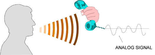
The term analog comes from the design of the telephone: a microphone in the telephone handset is placed in the path of the sound pressure waves coming out of the speaker’s throat. As the sound pressure waves hit the microphone, they change its electrical characteristics.
We use the fact that the electrical characteristics of the microphone change as the sound pressure waves hit it to make a voltage on the telephone wires change.
This voltage is a representation or analog of the sound pressure waves.
This is all we mean by analog: representation.
The voltage on the wires is an analog of the sound pressure waves coming out of the speaker’s throat.
People then stretch the terminology to call the two copper wires which form the telephone line an analog circuit, which is not very accurate.
It would be more accurate to call the loop "two copper wires that were designed to be able to carry a voltage that is a direct representation of the strength of the sound pressure wave impacting on the microphone". But that takes a long time to say, so people call them "analog circuits".
Note that the only thing analog in this story is the method for representing information on the copper wires.
We can use digital techniques on the same wires.